
Dance Floor Installation Scope and Key Takeaways
This guide gives installers and crew chiefs a repeatable method for laying a modular dance floor on their first assignment. It covers site checks, module selection, panel interlocking, edging, corners, walkway access, quality control, strike and reload, and the boundary between dance-floor and stage-deck work. The reader’s job is to turn an unfamiliar kit into a controlled sequence and arrive with every panel accounted for.
Key Takeaways
- Choose the module format before unloading; panel size affects coverage, handling weight and the number of joints in the field.
- Build the panel field from a fixed reference line instead of placing modules wherever space remains in the venue.
- Engage the precision locking mechanism as each module is positioned, then check the completed joint before continuing.
- Keep straight edging, corners and walkway corners as separate inventory so the crew can identify each part at installation.
- Inspect joints, height continuity and perimeter fit before opening the floor to guests or performers.
- Treat the published setup claim as a product benchmark, then plan around the actual access route and site conditions.
- Strike in reverse build order and reconcile every panel and edge part before the kit returns to inventory.
How to Use This Guide
Reader’s job: Turn the supplied product system into a defined installation plan. Before the truck reaches the venue, the crew chief should identify the module format, separate panels from perimeter parts, confirm the intended access route and assign clear responsibilities for each part of the build.
Installation sequence: Prepare the site, establish the module field, lay and lock the panels, fit straight edging and the correct corners, inspect the completed floor, then reverse the sequence during strike. The same order should appear on the crew’s sheet and in the reload plan.
Select and Inventory the Right Module
Compare the Published Panel Formats
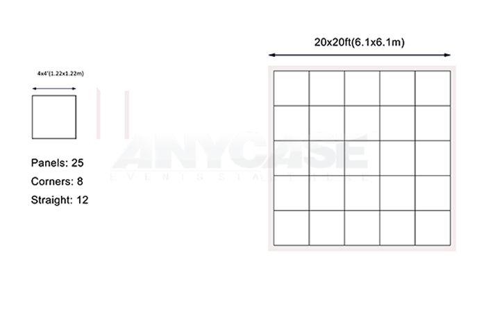
Module format: The seamless dance floor range includes four-by-four-foot, three-by-three-foot and one-metre panels. Each is a modular panel with tight precision locks, so the correct format is the one that suits the footprint, access route and handling plan rather than the one that happens to be closest to the vehicle.
| Panel format | Metric dimensions | Imperial dimensions | Plan area per panel | Weight |
|---|---|---|---|---|
| Four-by-four-foot panel | 122 × 122 × 2 cm | 4 ft × 4 ft × 0.78 in | 1.4884 m² | 19.5 kg / 42.9 lb |
| Three-by-three-foot panel | 91 × 91 × 2 cm | 3 ft × 3 ft × 0.78 in | 0.8281 m² | 11.8 kg / 25.96 lb |
| One-metre panel | 100 × 100 × 2 cm | 3.28 ft × 3.28 ft × 0.78 in | 1.0000 m² | 13.5 kg / 29.7 lb |
Panel area: Calculated from the published metric dimensions, the four-by-four-foot panel covers 1.4884 m², the one-metre panel covers 1.0000 m² and the three-by-three-foot panel covers 0.8281 m². The four-by-four-foot module therefore provides the largest plan area per panel, while the one-metre panel occupies an exact one-square-metre plan footprint.
Handling weight: The same three panel formats weigh 19.5 kg, 13.5 kg and 11.8 kg respectively. A larger module can reduce the number of pieces in the field, but it also increases the load carried during each panel movement. The module choice should therefore balance coverage against the crew’s handling method and the number of joints to inspect.
Published setup claim: The dance-floor product page presents a published 2-person, 10-minute, no-tool setup claim for the interlocking system. This should be recorded as a manufacturer benchmark rather than treated as a promise for every footprint, access route, site condition or crew experience.
Build the Parts Inventory Before the Build
Panel: Panels create the main dancing surface. Edging finishes an exposed straight edge. Corner parts finish outside corners where two straight runs meet. Walkway corner parts are identified separately for the access section of the layout. These roles should remain visible in the kit list and on the storage bins.
| Part | Published dimensions | Published weight |
|---|---|---|
| Four-foot straight edging | 122 × 7 × 2 cm | 0.9 kg / 1.98 lb |
| Four-foot corner | 129 × 7 × 2 cm | 0.9 kg / 1.98 lb |
| Four-foot walkway corner | 129 × 7 × 2 cm | 0.9 kg / 1.98 lb |
| Three-foot straight edging | 91 × 7 × 2 cm | 0.7 kg / 1.54 lb |
| Three-foot corner | 98 × 7 × 2 cm | 0.7 kg / 1.54 lb |
| Three-foot walkway corner | 98 × 7 × 2 cm | 0.7 kg / 1.54 lb |
| One-metre straight edging | 100 × 7 × 2 cm | 0.8 kg / 1.76 lb |
| One-metre corner | 107 × 7 × 2 cm | 0.8 kg / 1.76 lb |
| One-metre walkway corner | 107 × 7 × 2 cm | 0.8 kg / 1.76 lb |
Interlocking panel: Each panel connects tightly through precision locking mechanisms, creating a continuous surface without visible gaps or height differences. The crew should therefore treat alignment and lock engagement as one operation: a module is not placed until its position and connection are both correct.
The dance floor collection also includes illuminated, pixel, parquet and outdoor variants. They serve different layouts, but the basic installation discipline remains the same: confirm the module family, establish the reference line, lock the field and fit the perimeter parts designated for that system.
The First-Time Installation Sequence
Prepare the Venue and Fix the Layout
Site condition: Inspect the proposed floor area before unloading. The base must be suitable for the intended installation, and uneven or unsupported sections should be resolved before the first panel is positioned. Mark obstructions, changes in level and the route between the loading point and the finished floor.
Reference corner: Choose a corner that can serve as the origin of the module field and remain accessible during the build. Set the first module line from that point, then extend the layout in both directions. This prevents the crew from drifting into an irregular outline as the number of modules increases.
Module field: Separate the finished dancing area from the walkway and perimeter before parts leave the transport case. Decide where straight edging will run, where corners will meet and where the walkway access belongs. The inventory and floor plan should use the same names so the installer does not have to interpret a part label at the perimeter.
Lay and Lock the Panel Field
Unload the selected module format first and keep it clear of the reference line. Place the initial modules against the marked edge, align their frames and engage the locking mechanism before adding the next piece. Do not push a misaligned module into position; correct the reference line or the preceding joint first.
Locking mechanism: The precision locks are the connection system that turns separate panels into a continuous surface. Each connection should be engaged deliberately and checked immediately. The crew should work in a consistent direction across the field, returning to the starting line whenever the working edge drifts.
Continue the same sequence until the planned panel field is complete. Check the visible joints and height continuity before moving to the perimeter. If the field is not square or its edge does not follow the plan, resolve that issue before the edging hides the working line.
Close the Perimeter with the Correct Parts
Straight edging: Fit straight edging only after the panel field has been aligned and checked. It covers the exposed straight section of the panel boundary and gives the crew a defined finished edge to inspect during handover.
Corner: Use the designated corner where the perimeter changes direction. Although the published corner and walkway corner dimensions match within each format, their installation roles are different. Identify the part by its label and position rather than selecting by shape alone.
Walkway corner: Fit the walkway corner where the access route meets the perimeter. Confirm that it sits with the walkway modules and does not pull the finished edge away from the panel field. The access route should remain clear when the floor is handed over.
Strike and Reload
Strike order: Reverse the build sequence. Remove the walkway corners and perimeter parts first, then unlock and lift the panels in the reverse order used for installation. Keeping the original module order prevents the kit from becoming a mixed inventory when it returns to the warehouse.
Reload plan: Sort panels, straight edging, corners and walkway corners into separate groups and reconcile them against the dispatch list. Record any missing or damaged part before the equipment leaves the venue. The next crew should receive the same organized kit that the first crew received.
Crew Roles and Handling
Assign Clear Responsibilities
Crew chief: Owns the venue plan, reference line, module choice and final handover check. The crew chief should stop the build if the field no longer follows the plan, rather than allowing perimeter fitting to conceal a layout error.
Installer: Positions each panel, aligns the connection and confirms that the precision lock is engaged. The installer should work continuously from the marked edge and communicate any drift before the next module is added.
Runner: Retrieves the next module and the required perimeter part from the sorted kit. The runner should keep panels clear of the working edge and bring parts forward according to the build sequence, reducing unnecessary movement around the installation.
Handle Panels as Inventory
Panel handling: Published panel weights range from 11.8 kg to 19.5 kg. The crew should choose a handling method appropriate to its members and site conditions; the product weight alone does not establish that a panel can be carried safely by a particular person or team.
Edge protection: Straight edging, corners and walkway corners are lighter than the main panels, but each has a defined position. Keep them identified and supported during the build so a corner is not installed as straight edging or moved to the wrong perimeter during a rush.
Missing part: Count the panel family and each perimeter category before departure and again after strike. If a part is missing, resolve it before the kit is closed and the crew leaves the site rather than discovering the shortage at the next assignment.
Quality Control and Failure Modes
Inspect Before Handover
Joint check: Walk the complete panel field and inspect every visible joint and connection. The intended result is a continuous surface without visible gaps or height differences. A joint that does not meet that condition should be corrected before guests or performers enter.
Perimeter check: Confirm that straight edging follows the exposed panel edges, corners sit at direction changes and the walkway corner completes the access area. Check that no loose perimeter part projects into the circulation route and that the finished edge matches the approved layout.
Diagnose the Problem at Its Source
Uneven base: Correct an uneven or unsuitable base condition before treating the joint as a product fault. The panel field depends on consistent support beneath the module field, so changing the alignment may conceal rather than resolve the underlying issue.
Misaligned field: Return to the reference corner and the first installed row when the working edge drifts. Correcting one joint at the far end can transfer the error elsewhere. Re-establish the intended line before continuing with more panels.
Wrong part: Check the part label and required position instead of relying only on visible dimensions. Matching dimensions within one format do not make a corner and a walkway corner interchangeable in the finished layout.
Missing latch: Stop when a connection is not fully engaged. The precision locking mechanism should secure each panel to the next, so an incomplete connection must be inspected and corrected before the perimeter is closed.
Dance Floor, Stage Deck and Riser Boundaries
Define Each Component Before Combining Workstreams
Stage deck: A stage deck forms the platform surface. It is not another name for a dance-floor panel, even when both products are used at the same event. Review the stage deck system separately from the floor modules and mark the two work areas on the site plan.
Riser: A riser is the support structure beneath a stage deck; it determines the platform elevation and supports the deck. ANYCASE folding stage risers are offered in 20 cm, 40 cm, 60 cm, 80 cm and 100 cm height options for compatible stage-deck configurations.
Aluminum tube: The published stage-riser material specification lists aluminum tube at 20 × 1.5 mm. The same system uses ABS plastic support points and an integrated locking latch system. These specifications belong to the riser, not to the interlocking dance-floor panels.
Related equipment should remain part of its own inventory plan. The portable stage range and aluminum stage range are separate from the modular dance-floor system, even when the venue needs both products.
Follow the Deck-and-Riser Sequence Without Confusing It
For stage work, unfold the riser while locating the correct arrow, position it beneath the designated deck support points and engage the integrated connection. Ensure that the latch pins enter the ABS plastic holes properly before the platform is treated as complete.
Connect the deck units to create the required platform, then use the wrench key to lock the decks from the top surface. This tool requirement is specific to the stage-deck sequence; it does not change the published no-tool claim for the interlocking dance-floor system.
Stage risers are not recommended for uneven or sloped ground, including uneven grass. All ABS plastic support points must rest on the same level surface for stability and proper load distribution. The dance-floor crew and stage crew should therefore keep their reference lines, support checks and handover records separate.


B2B Procurement and Installation FAQ
Plan Procurement Around the Complete Kit
Specify the module family, panel quantity, straight edging, corners, walkway corners and packaging format as separate order lines. This prevents a rental company from receiving panels without the perimeter parts needed to complete the installation. For alternative visual or environmental requirements, review LED starlit dance floors, pixel dance floors and waterproof outdoor dance floors as separate product families rather than interchangeable variants.
For mixed-event inventory, keep the dance-floor kit, stage decks, risers and their connection requirements in separate storage and dispatch records. The supplier should receive the intended module format, perimeter requirements and project application before the final kit configuration is approved.
Buyer FAQ
How many people are needed to set the dance floor?
The published product figure states a 2-person, 10-minute, no-tool setup claim for the interlocking system. Treat that as a product benchmark. Actual crew allocation still depends on the chosen format, layout, access route, site condition and handover inspection.
Which panel format should a first-time crew choose?
Compare published plan area and panel weight together. The four-by-four-foot panel covers 1.4884 m² and weighs 19.5 kg, the one-metre panel covers 1.0000 m² and weighs 13.5 kg, and the three-by-three-foot panel covers 0.8281 m² and weighs 11.8 kg.
How do the panels connect?
Each panel uses precision locking mechanisms that connect tightly to adjacent modules. The crew should align the panel frame, engage the lock and inspect the joint before continuing. This creates the intended continuous surface without visible gaps or height differences.
What is the difference between edging, a corner and a walkway corner?
Straight edging finishes a straight exposed boundary. A corner finishes a point where the perimeter changes direction. A walkway corner is reserved for the access section. They should be identified by their role in the approved layout before installation begins.
Can the dance-floor kit also be used as a stage deck?
No such interchangeability is established in the supplied product information. A dance-floor panel forms part of the modular flooring system, while a stage deck forms a stage platform supported by a riser. Specify, store and inspect them as separate systems.
What should happen during strike and reload?
Remove perimeter parts first, then reverse the panel installation sequence. Sort the panels and perimeter components into their original inventory groups, reconcile every part against the dispatch list and record missing or damaged items before departure.
ANYCASE Production Capability and Process
Production Scope and Project Adaptation
ANYCASE manufactures portable stages, stage decks, risers, aluminum stages, truss systems, dance floors and related event equipment. Factory-based production can adapt stage support dimensions, configurations, surfaces and packaging for different B2B projects.
Folding stage risers collapse into a compact form for transportation and storage. Riser packaging can be specified in a carton, trolley or flight case according to the project inventory and handling method.
Order and Delivery Process
The project process starts with the event application and stage layout, followed by selection of the compatible deck and riser combination. ANYCASE then confirms support dimensions, configurations, surfaces and packaging. The approved specification moves into production, assembly and packing, after which the order is prepared as a defined project or rental inventory item.
